
No products
Product successfully added to your shopping cart
There are 0 items in your cart. There is 1 item in your cart.
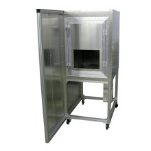
ESD Immunity Test Environment
Viewed products
-

ETS Firing Test System...
Range: ±100 to ±26kV Capacitors:...
Best sellers
-

Schaffner / Teseq NSG 435 ESD Simulator for IEC 61000-4-2
Programmable discharge voltage 200 V to 16.5 kV Stabilized charging...
$590.00 -

ESDGuns.com GRC Series Ground Cable w/ 470k Ohm Resistors for ESD Voltage Bleeding
Ideal for voltage bleeding to Ground Plane during Indirect ESD Immunity...
$199.00 -

Rent Keytek Minizap MZ-15/EC 15kV ESD Simulator Gun
Rentals Ship Immediately Purchase Options See: Used Keytek Minizap ESD...
$495.00 -

ESD Guns IF Insulating Foil for ESD Compliance Testing
Suitable for EN/IEC 61000-4-2 ESD immunity compliance testing...
$197.00 -

Teseq / Schaffner INA 405 Ni-Mh Battery Pack Refurbishment for NSG 435 ESD Gun
ESD Guns can refurbish your existing INA 405 battery pack. Expected...
$275.00 -

Haefely ONYX 16 kV ESD Generator Gun
Rental Package IncludesAir and Contact Discharge Tips Output...
$595.00 -

Teseq NSG 437 Electrostatic Discharge (ESD) Simulator Gun for GR-1089 & IEC 61000-4-2
Air- and contact-discharge to 30 kV Color touch panel control Advanced...
$895.00 -

3ctest EDS 20H Hand-held 20kV Electrostatic Discharge ESD Simulator
Air- and Contact- Discharge: 1000 Volts - 20kV ±5% Rise time: 0.6-1ns RC...
$476.00
ETS Firing Test System Model 931
 View larger
New
- Range: ±100 to ±26kV
- Capacitors: 100pf to 0.5μf
- Resistors: 0, 500, 1500 and 5000 Ω
- Custom resistor and capacitor networks

Download
More info
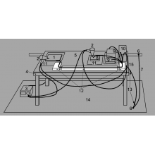
The Model 931 Firing Test System is designed specifically to determine the ESD susceptibility of pyrotechnic devices, powders and liquids. The 2-piece Electrostatic Discharge Simulator consists of a Control Unit housing all low voltage electronics and controls plus a 4½-digit LED voltage level display and a Discharge Unit containing the HVPS, polarity reversing module, plus capacitor and resistor selector modules.
The Model 931 produces discharge pulses from ±100 Volts to ±26kV. Energy is stored in capacitor banks during the charging cycle. A discharge pulse is produced when a high voltage gas filled relay disconnects the charged capacitor from its charging source and connects it to the output of the FTS Discharge Unit. The energy storage capacitor bank is installed inside the Discharge Unit. Discharge resistors are installed within the Discharge Unit or contained in individual plug-in modules depending on system configuration. R/C values must be specified at time of order. Additional capacitor and resistor modules can be plugged into the SPARE capacitor and resistor input connectors on the front panel of the Discharge Unit. Standard capacitor values range from 100pf to 0.5μf and resistor values range from 0 to 5,000 Ohms. Non-standard capacitors, resistors and voltages up to 30kV may be special ordered. A 25 MegOhm resistor permanently connects the output to ground to bleed off residual voltage after a discharge plus an interlock cable connected to a user supplied switch removes power to the HVPS when the switch is open. Spring-loaded ARM and DISCHARGE switches control the charge/discharge cycle. The AUTO Mode allows for up to 9 discharges while holding down the ARM and DISCHARGE switches. Test Standards: Many applications require the determination of the energy threshold for ignition by electrostatic discharge of varying intensities. Energy is determined by the equation E=½CV2. Resulting data can then be used to characterize the probability of ignition due to an ESD event. MIL-STD-1751A, (Group 1030 Test Methods) along with MIL-STDs 1512, 1576 (Method 2205) and MIL-STD-331C cover the most common test standards for electrostatic discharge sensitivity testing.
- MIL-STD-1751A (Powder testing): Methods, 1031,1032,1033,1034
- MIL-STD-1576 (Device testing): Methods, 2205
- MIL-STD-1512 (Device testing)
- MIL-STD-331C (Device testing); Notice 3
Discharge Waveforms:
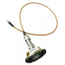
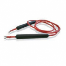
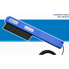
The discharge waveform at the output is a function of the R/C network and the output impedance. When the output resistor is 0 Ohms the discharge is a damped oscillation and its peak voltage is a function of the output impedance. On the other hand, when the output resistor has a finite value such as 500 Ohms the waveform is an exponential decay where the peak voltage is primarily a function of the output resistor. Typical waveforms at 5kV are shown using an ETS Model 949 IEC specified Test Target (transfer ratio = 1V/amp). C=500pF/R=0Ω Standard Configurations: C=500pF/R=500Ω The Model 931 can be configured to meet virtually any customer requirement including custom R/C networks and pin selection of multi-pin devices. The following standard systems listed below include a 6 ft (183cm) HV Output/Gnd cable assembly with banana plugs and removable alligator clips plus a 6 ft (183cm) interlock cable for connection to a user supplied interlock switch.
- A: (Mil STD 1512, 1576, 331C) Vmax = ±26 kV; C = 500, 1000, 2000 & 5000 pF; R = 0, 500, 5000 Ω
- B: (MIL STD 1512, 1576, 331C, 1751A-Methods 1032 & 1033) Vmax = ±26 kV; C = 250, 500, 1000, 2000, 5000, 10,000 & 20,000 pF; R = 0, 500, 5000 Ω
- C: (Expanded B configuration) Vmax = ±26 kV; C = 100, 250, 500, 1000, 2000, 5000, 10,000 & 20,000 pF; R = 0, 500, 1500, 5000 Ω
- D: (MIL STD 1512, 1576, 331C, 1751A-Methods 1031, 1032 & 1033) Vmax = ±26 kV; C = 100, 250, 500, 1000, 2000, 5000, 10,000 & 20,000 pF; R = 0, 500, 5000 Ω Vmax = ± 6 kV; C = 0.05, 0.1, 0.25, 0.5 Ff (MIL STD configuration)
Accessories

11 other products in the same category:
-
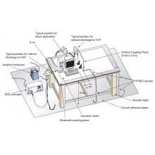
ESD Test Table/Bench with Coupling Planes and Grounding Cables
-
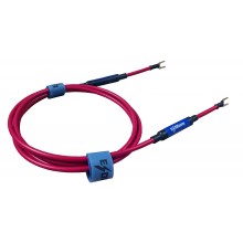
ESDGuns.com GRC Series Ground Cable w/ 470k Ohm Resistors for ESD Voltage Bleeding
-

ESD Guns IF Insulating Foil for ESD Compliance Testing
-
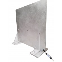
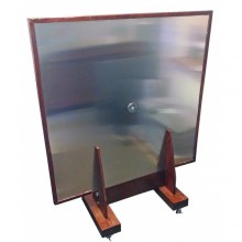
Rent VCP Vertical Coupling Plane for Indirect ESD Testing
-
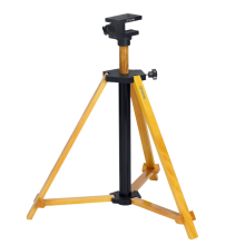
Industrial Wood Tripod to mount ESD Simulators
-
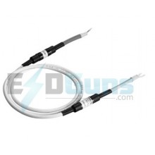
Teseq / Schaffner INA 414-2M Grounding cable with 470kOhm resistor at each end, 200cm
-
EM Test EAS 30 Grounding Set with 1.4m Cable and Two 470kΩ Resistors
-
50mm Insulation Block Set for ISO 10605 Automotive ESD Test Setup
-
The EMC Shop ESD-BR Electrostatic Removal Brush
-

Set-up & Apparatus for Automotive ESD Testing to ISO 10605
-

ISDP Insulation Support/Dissipative Mat per ISO 10605